I think the DashScan2 display solution is the best way to add an extra display to the Fiero without butchering the Fiero gauge cluster irreversibly. And LEDs are just about the only affordable solution considering the wide temperature range required for automotive use.
I kept getting requests on how to obtain a DashScan2, and well, I just didn't have the time to build them for everyone. Plus, the two LED displays used in the display unit kept getting more expensive every year. So I have decided to release the schematics and processor image file to allow everyone to build the display unit themselves. If you dare to solder surface mount parts, you should have no trouble building it. Please note that this is only the display unit, not the whole DashScan2! But building DashScan2 yourself would be a whole different challenge level beyond most DIYers. Anyway...
The display is not limited to DashScan, by the way. The input is RS232 compatible, and even allows VT52 terminal commands like clear screen, so it can be used with other embedded homebrew projects as well.
But please note: I retain the copyright, and you are only granted to build this display unit for your own use! It is not allowed to be incorporated into commercial projects or built for profit. If you want to license this display for commercial use, please eMail me!

The schematics are very simple. There are only four connections, two of which are power and ground. Please note that the display only operates on 5 Volts, which it expects to get from the controlling processor board, i.e. DashScan2! If you build the display and want to bench test it, do not power it with 12V or you will destroy most components!
The other two inputs are the data input and the dimmer input. The data input is RS232 compatible, but also accepts TTL level. You can hook up a RS232 cable to this input and control the display via a terminal program on a PC. The dimmer input is 12V compatible and is connected to the parking lights circuit (brown wire) on the Fiero.
Most of the components are surface mount parts, sorry about that. Please refer to the eagle circuit board file for what things should look like.
IC2 is a three pin, active high reset controller, and yes, it is required. If you run the display without this controller, there is no reliable reset pulse in hot weather, and the display CPU "hangs". There are a variety of parts from Maxim and other companies, I usually use the MCP810-4.63V.
The processor is an AT89C2051 from Atmel, be sure you don't get old stock with a limited temperature range - suffixes -PA (Automotive) -PI (Industrial) and -PU (Universal) are fine, -PC (Commercial) may give you problems. Program it with this file with the appropriate programmer. And don't be cheap and put the CPU in a socket.
The displays need to be mounted at a 90 degree angle. I use Conrad Electronic #188344. Something else may work equally well.
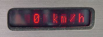
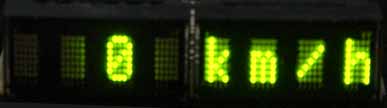
And finally, and most importantly, the Osram Semiconductor LED display modules themselves. They are available in four colors:
And don't forget to mount a filter plexiglass of the appropriate color, it will improve readability 300%.
If you want to have a circuit board made, here is the Eagle file, most PCB houses accept eagle files. But I sometimes have a few boards here, contact me if you want one, I can mail one to you at cost.
Okay, if you have read this far and still want to go ahead and build your own, just do it. But please don't expect me to support you if you don't get it to work! Believe me, the circuit works just fine - if yours doesn't work, you have made a mistake somewhere...
There have been
visitors to this site since May 31, 2000.