The story is simple: some time in April 2002 my tach died when I was accelerating my 87GT
on the highway. The RPM redlined and then dropped to zero. My gut feeling told me it was
my tach filter, and after replacing it with the one from my 85GT, my suspicion turned
into certainty. Nothing is easier than getting a new tach filter, right? Wrong!
The tach filter has been discontinued from GM for some time, and the only alternatives
were getting one from Rodney Dickman or making one
yourself. Both alternatives were not really appealing, since Rodney's version at the time did not
look stock, and making one myself would have probably looked even worse.
Well, I've had these schematics on my
site for years. But I never knew if these values were correct, or what the internals
of my tach filter really looked like. Maybe the old one was repairable? A quick check
revealed that there was no resistance from input to output. Disassembly time!
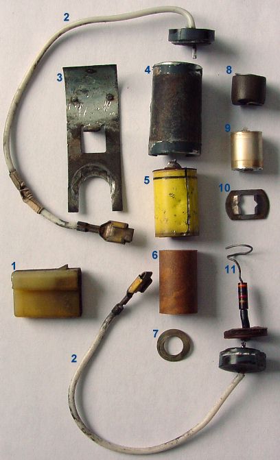
At first I removed the contacts (2) from the connector (1) and removed the
grounding bracket (3) from the main filter (which is 17mm in diameter and 44mm long). The
bracked is spot-welded to the metal cylinder (4) in three places. The cylinder is not
completely metal though, the two ends are epoxy or something similar to protect the internals
from water, etc. I guess. You can find the ends of the cylinder by scraping the
paint and tape from the filter. I cut a groove 1mm deep all around both ends
of the cylinder, and spread the groove with a screwdriver: the epoxy ends popped off
easily. So this cylinder is only 32mm long, the rest is epoxy.
Next came two solder joints which I unsoldered. I then cut through the cylinder
from end to end and "peeled" it off the internals. The internals are as cheap
as can be...
Inside the can there is another metal can (5) that has the solder contact on one end.
this contact touches the actual inner can. Inside this can is a cardboard
isolation cylinder (6) to keep the internals from touching the inner cylinder's walls. Anyway,
Inside that can is a 10k resistor (8), which
is inside something that probably used to be foam (8). Both ends of the resistor are curled
up. One end touches a little metal spring (7), the other end touches the capacitor (9).
The capacitor is wrapped around a 3k resistor (11), and the 3k resistor's end is isolated
from the capacitor and soldered to the other solder cap. The unsoldered end of the 3k
resistor was also curled up on top of the capacitor, and made contact with the capacitor
and the 10k resistor. Finally, the other end of the capacitor made contact with a
little spring (10) that extended past the contact cap to the outer cylinder.
Measuring the capacitor showed that the value is 47nF. So the schematics
have been correct all these years. But why did this unit fail? Well, nothing is soldered
inside of it! All components just touch, and vibration, oxidation and aging do the rest.
Can you fix it? Well, it depends. To get to the internals, you have to destroy the outer
cylinder. After that, you can disassemble the internals, and probably restore contact by soldering
some connections. But you won't be able to restore the original look.
Rodney now offers a replacement tach filter that does look stock, but it is a bit pricey. At least there is
an alternative now, and a NOS unit (if you can find one) won't be less, and will have oxidized on the shelf as well.
Oh, if you have accidentally taken the tach filter apart, the image of the connector may come
in handy, and the longer one of the two wires is the input (coil end), the shorter one is the
output (tach end).
There have been
visitors to this site since May 31, 2000.
 At first I removed the contacts (2) from the connector (1) and removed the
grounding bracket (3) from the main filter (which is 17mm in diameter and 44mm long). The
bracked is spot-welded to the metal cylinder (4) in three places. The cylinder is not
completely metal though, the two ends are epoxy or something similar to protect the internals
from water, etc. I guess. You can find the ends of the cylinder by scraping the
paint and tape from the filter. I cut a groove 1mm deep all around both ends
of the cylinder, and spread the groove with a screwdriver: the epoxy ends popped off
easily. So this cylinder is only 32mm long, the rest is epoxy.
Next came two solder joints which I unsoldered. I then cut through the cylinder
from end to end and "peeled" it off the internals. The internals are as cheap
as can be...
At first I removed the contacts (2) from the connector (1) and removed the
grounding bracket (3) from the main filter (which is 17mm in diameter and 44mm long). The
bracked is spot-welded to the metal cylinder (4) in three places. The cylinder is not
completely metal though, the two ends are epoxy or something similar to protect the internals
from water, etc. I guess. You can find the ends of the cylinder by scraping the
paint and tape from the filter. I cut a groove 1mm deep all around both ends
of the cylinder, and spread the groove with a screwdriver: the epoxy ends popped off
easily. So this cylinder is only 32mm long, the rest is epoxy.
Next came two solder joints which I unsoldered. I then cut through the cylinder
from end to end and "peeled" it off the internals. The internals are as cheap
as can be...
 Measuring the capacitor showed that the value is 47nF. So the