The information in this article can be used to troubleshoot or repair your tach if you have some knowledge of electronics, but it can also be used to modify or adjust your tach if you are doing an engine conversion or try to put a backlit V6 tach into an L4 or other car. And this modification can be done by anyone who can use a soldering iron. If you find this topic interesting, read on...
Tracing the traces on the circuit board revealed, that GM has for the most part used the application circuit from the application notes. A few values were changed, but for the most part they are identical.
One change is the supply voltage going to Pin 13: In the application note this voltage is the same voltage applied to the zener diode feeding Pin 1. GM used only D1, R4 and D3 to feed Pin 1. Instead, GM stabilized this voltage through a 20 Ohm resistor and another diode before feeding it to Pin 13. Only a subtle change, but I thought I'd note it.
Another noteworthy detail is that most resistors from the schematics (R1, R2, R5, R7 and Rreg) are contained in a "thick film resistor chip". This is the "calibration" chip. This way, GM could eliminate variable resistors and trim the ones on the chip. If you look closely, you can see the mark where the resistor has been cut to increase its value.
If your tach gauge is shot, it is most likely that the integrated circuit itself is shot. Instead of trying to get the GM part, the LM 1819 should be much easier to come by. It is marked obsolete, but you may still be luckier than getting the GM equivalent. One possible source is electronics-plus which list the NTE01670 (which seems to be pin- and function compatible) for $3.95.
If you want to modify the gauge for a different engine configuration, the data sheet tells you how to calculate the values needed. Specifically, it tells you that a capacitor and a resistor parallel to it going from Pin 5 to Pin 8 are responsible for the needle deflection. Now, many sources will tell you to replace the capacitor with a different value, and this will work. But capacitors are usually not adjustable, so you have to experiment a lot until you get the proper reading. But there is an easier way.
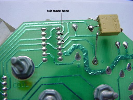
Cutting the trace to the resistor and replacing it with a variable resistor is much more accurate than trying to find the proper capacitor value that fits. Look at the image for information on where to cut and where to solder the variable resistor or fixed resistor(s). This tach is from an 86GT, and the original value of the calibration resistor was 280k, yielding a reading of 1200rpm @ 60 Hz input frequency (60 Hz = 3600 pulses per minute, and a V6 fires three plugs per rev, so the number of pulses must be divided by three).
If you want to put this tach into a regular L4 engine, there will only be two pulses per rev, so the tach must read 1800rpm @ 60 Hz input frequency. The tach reading and the resistor value are linear, so to in other words, to calibrate the tach for the standard L4, the original value must be multiplied by a factor of 1.5. The resulting resistor value would be 280k * 1.5 = 420k.
Now, if you have an L4 with a DIS (distributorless) engine, since there are two coils, each coil only needs to fire once per rev, so the tach needs to be adjusted to 3600rpm @ 60Hz input frequency. The resulting resistor value would hence be 840k.
If you have access to a frequency generator, you can generate 60Hz, install a variable resistor (1 Meg resistance), and adjust until you get the proper reading. If you don't have that, just measure the original resistor and calculate the value for the variable resistor before you solder it in. If you don't have a digital ohmmeter either, well, go to Radio Shack and get a number of resistors that add up to the desired resistance (you have to put the resistors in series if you're adding them up). Either way, this method is more exact than trying a multitude of capacitors. Modifying the resistor is the right way of doing this, after all, this is what GM did as well. Another way would be to change the capacitor value, and only use the variable resistor for fine tuning, but why invest more work than necessary. The modification described above works well and only takes about 2 minutes.
The information above was derived from the National Semiconductor datasheet and from reverse engineering a Fiero tach board. Use the above information at your own risk!
There have been
visitors to this site since May 31, 2000.