The tilt steering column disassembly seems to be one of the last great mysteries of our time. Nobody likes to do it, but when you do'it's really not all that bad. At least it seems that way to me. Most people don't know how to disassemble it, and the description in the Factory Service Manual is sketchy at best. So I have decided to document the process of tearing into the column, when it was time for me to do so.
This procedure should be useful if you're trying to do one of these repairs:
I tried to take as many pictures as possible, but I still may have missed a step here or there. If I did, I apologize, but I still hope you find the pictures informative. Some of the writing has become a bit fuzzy due to the JPEG compression, but GIFs were just too large.
Some of the things described here can be done without removing the column from the car, however the deeper you have to go, the easier things get with the column out of the car. Plus, it's really simple to remove the column and put it back in. It's so much easier to do everything on a desk instead of crammed under the dash! So, I'd recommend to remove the steering wheel and locking plate while the column is in the car, and then remove the column from the car.
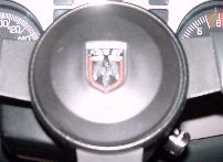
Start off by disconnecting the negative (-) battery connection. This is important, since you'll be fiddling around with the ignition switch, and you don't want to cause any shorts. Next remove the center cap/horn button (depending on your steering wheel). Remove the horn switch contact by pushing it in and turning it 1/4 turn counterclockwise.
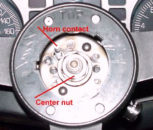
Remove the clip (if present), center nut (22mm), and pull off the steering wheel. You will need a steering wheel puller for this. You can get it e.g. at Sears. or just about any automotive supplier. Do not attempt to remove the wheel without this tool! Some wheels are loose enough on the shaft to be pulled manually, but don't use any brute force approach!
 |
 |
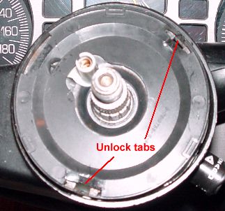
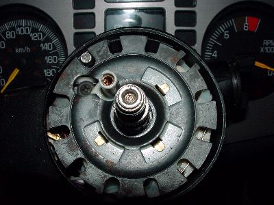
Next remove the plastic lock plate cover by unlocking the tabs with a screwdriver.
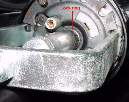
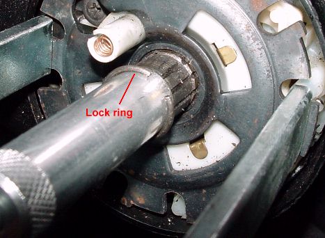
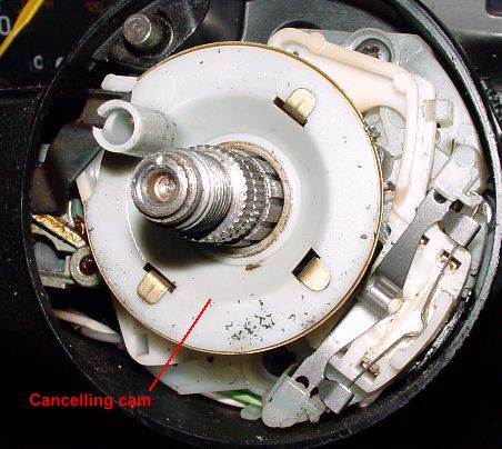
Once that's out of the way, you should use a lock plate compressor to push and hold down the lock plate. This allows you to slide the c-clip retainer onto the tool and release the spring pressure (you can see this in the pictures). Remove the lock plate and cancelling cam. Be careful not to lose the spring located in the cancelling cam tower! Remove the Hazard warning switch with a philips screw driver. The switch consists of two parts, plus a spring and a screw. Don't lose them either.
 |
 |
 |
 |
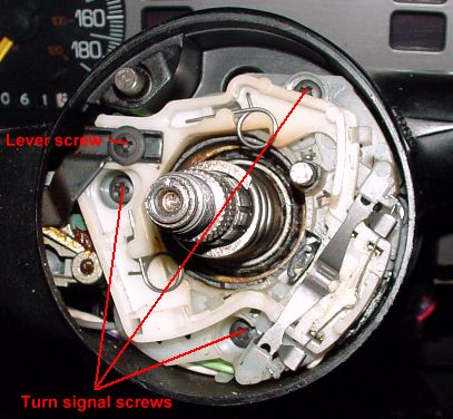
Remove the lock plate spring from the shaft. Next remove the three screws from the turn signal switch. You must move the turn signal switch in each direction to gain access to all screws. Now remove the philips screw from the turn signal lever. Pull the turn signal stalk from the column with the wiper in the off position.
This is where I took the column out of the car. Remove the 11mm bolt attaching the column to the U-joint, and remove the two 15mm nuts and the two 15mm bolts holding the column in the car. Carefully lower the column. Disconnect the turn signal connector, the wiper switch connector and the cruise connector, if equipped. Remove the ignition switch connector. This is a two part connector, consisting of a black and a white part, both of which have two locking tabs, so don't force the connectors off. Remove the high beam switch connector (locking tabs!). If you have an automatic transmission, remove the park lock cable by removing the two tiny philips screws from the ignition switch. The column should now be free and you can carefully remove it from the vehicle.
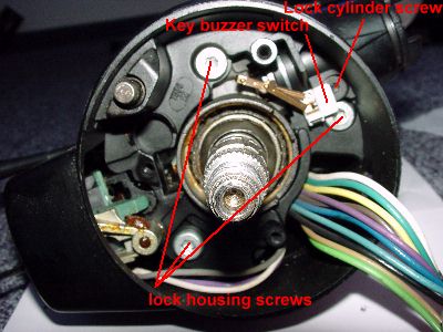
Put the ignition lock in the RUN position and carefully remove the key warning buzzer switch with a paper clip. Remove the TX20 bolt holding the ignition lock cylinder. Remove the lock cylinder.
 |
 |
Remove the three TX30 screws attaching the ignition lock housing to the column. When you pull the lock housing off, the high beam actuator may fall out. Getting it back in place can be fun if you're putting things back together. So beware!
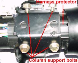
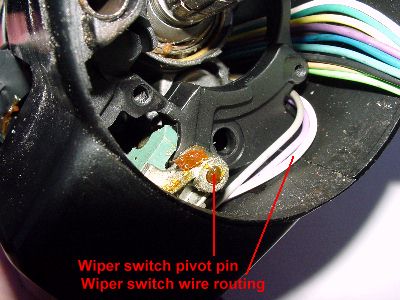
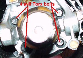
If you're going to remove/replace either the turn signal switch or the wiper switch, remove the four bolts shown in the picture below, and the harness protector. You can fiddle connector and harness through the column even if it doesn't seem like it will fit. It will. When you reassemble, these bolts have to be put back in in the right order, and torqued to spec. Check the Helms manual for the recommended torque values for your vehicle.
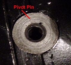
To remove the wiper switch, push the pivot pin out of the housing, and remove the switch.
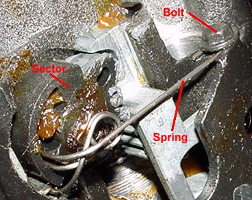
Remove the sector and spring by punching the shaft that goes to the lock cylinder through the sector with a screwdriver. The spring is held with a small bolt. Put the bolt back in place so you don't lose it.
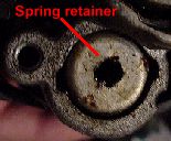
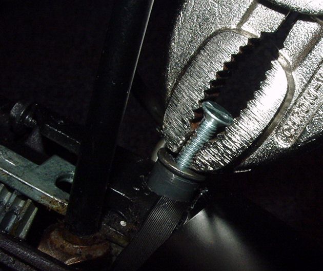
Next you have to remove the tilt mechanism spring retainer. This is the silver cap with the small rectangular hole. Insert a screwdriver, push down and make 1/4 turn counterclockwise to disengage the retainer. Remove the spring and retainer and set aside.
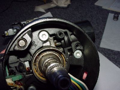
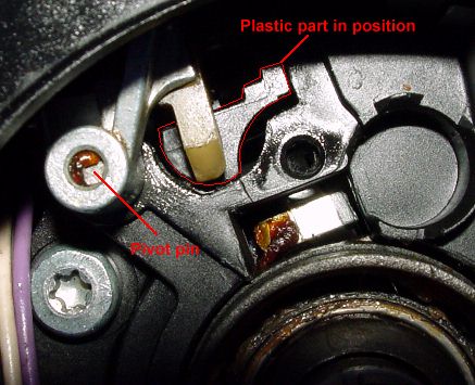
Reassembly is basically the reverse of the above. When reassembling, use a torque wrench to torque everything back to specs. You don't want the column to come apart when you're going 65 mph in heavy traffic! About the only tricky part when putting the column back together is the high beam switch actuator. Make sure the actuator is engaging the switch, and hold the column upright. The grease will "stick" the plastic part to the lower column shroud. Install the lock housing from above, and try to keep the plastic part in place. The picture shows what it should look like if you did it right. Install the turn signal stalk now to check if the high beam actuator works.
Grease is also a great helper to keep the balls inside a ball bearing, just a hint.
If you have any comments or suggestions (or additions), please feel free to contact me! Oh, and whatever you do, you do it at your own risk. If you find these pictures helpful, great, but if you break something or I made a wrong somewhere, don't blame me for anything, just let me know and I'll correct it.
There have been
visitors to this site since May 31, 2000.