First of all, let me say the original idea goes back to Don Middleton ("KlingonFiero") who in 2003 put a Caprice/Buick Roadmaster digital cruise into his 1984 Fiero. I first heard about a digital cruise in DarthFieros thread on PFF and his instructions to put a digital cruise into a V6 Fiero. He installed the digital cruise in a Fiero in combination with a 7730 ECM, which provided the signal the digital cruise control requires.
I was intrigued by the idea, because my vacuum operated cruise was inoperative once again, and I liked the cleaner look of the digital cruise in the Fiero's engine compartment. But initially I was overwhelmed by the information in the thread on Pennocks describing all the problems related with the installation of the digital cruise, so I backed off at first. The main reasons I didn't go ahead with the conversion was
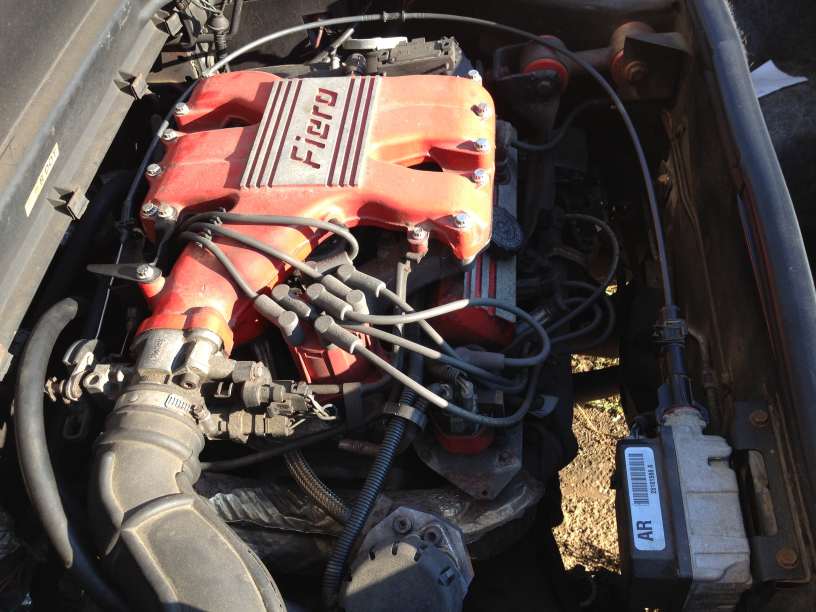
Things changed when I was stuck in Detroit due to the ash cloud from Eyjafjallajokull - I had time to go junkyarding and sought after a donor digital cruise with the code letters "AR" and the long throttle control cable. Needless to say, it was easy to be found, and under $10, so I bought two, along with the mounting brackets and connector pigtails.
As mentioned above, the procedure looked a bit confusing at first. After understanding what was involved I decided to alter the instructions slightly, because there are three issues with the original plans that I didn't like:
You may not consider the latter two points a big deal, but they are. You don't want the cruise to rev up your engine if you press the clutch pedal without pressing the brake, and the "two-brake-switch-redundancy" is also there for a reason: If the single brake switch fails, the cruise won't disengage when you brake, and will accelerate the car to compensate when you brake. Clearly not something you should desire. The redundancy takes care of this: if either the cruise brake switch or the stop lamp switch break, the cruise will disengage because the input signals are not consistent. And it is unlikely that both switches will fail at the same time.
GM had redundancy built into the original vacuum operated Fiero cruise as well: One switch going to the cruise module near the radio, the other going to a vacuum release valve that vents the vacuum if the brakes are applied.
What I describe here is obviously not the only way to do it, but it is the only way (that I see) that lets you upgrade to digital cruise without running extra wires through the firewall connector, and doesn't need an extra relay. If done this way, the wiring will look completely stock. Basically the idea is to use all wires already going back to the stock cruise module and not use any extra ones. It only works with V6 fastbacks with factory cruise though, at least the 87/88 L4's had the cruise built into the ECM, and the notchbacks don't have a separate brake wire, so things are different there.
Before I started I had a look at a Firebird service manual, which at some point also featured the same digital cruise. After comparing those instructions with Darth Fiero's instructions, I came up with these modified instructions, complete with schematics. I also changed the wiring to reflect the original wiring for a digital cruise to the detail. This may not be required, but may be one reason many people have problems getting their digital cruise to work.
Before starting the rewiring, the original vacuum operated cruise has to go, mainly because if you have the cruise and vacuum solenoid connectors hooked up and do the electrical modifications, you may fry something. So, disconnect the battery, then unhook the cruise cable from the throttle body, remove three 10mm bolts from the cruise servo bracked, one 10mm from the vacuum reservoir bracked, and disconnect the vacuum hose before disconnecting the wiring and removing all this crap from the car. Don't forget to put a vacuum cap on the vacuum line to prevent a vacuum leak!
 Okay, now we're ready to start the rewiring inside the car. You need to add a 4000ppm output to the Fiero speedometer.
Although I've heard that some people have success tapping directly into one of the VSS wires, I recommend against it, because the cruise input is
designed for a lower voltage input than the VSS's AC signal. The speedo modification is safer in my opinion, so here we go:
Okay, now we're ready to start the rewiring inside the car. You need to add a 4000ppm output to the Fiero speedometer.
Although I've heard that some people have success tapping directly into one of the VSS wires, I recommend against it, because the cruise input is
designed for a lower voltage input than the VSS's AC signal. The speedo modification is safer in my opinion, so here we go:
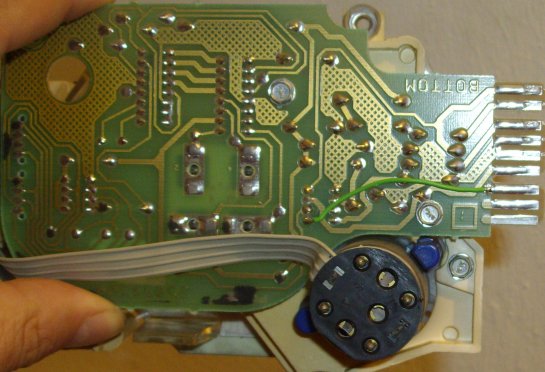
Remove the steering column cover and pull the connector from the speedo. The 88 V6 already has the 4000 ppm signal that the digital cruise requires on pin "M" of the connector, the previous years however don't have this luxury. Either get an 88 V6 speedo, or modify your existing (backlit!) speedometer to output the signal on this pin (see picture to the left for details). It is important you solder the correct pin here - the pin shown in the image is the "open collector" 4000ppm output the cruise module is designed for. The neighboring pin on the IC also carries a 4000ppm signal, but it is not open collector and also more than 5 Volts. While the digital cruise may survive the overvoltage, I recommend using the correct IC output for this conversion. Now you have a speedo with the required 4000ppm open collector output.
The next step will be to add a new terminal to the connector cavity "M" and route the 4000ppm signal to the cruise module (it's behind the carpet to the left of the radio). Remove the terminal position assurance (aka TPA, the whiteish bar that keeps the terminals from falling out). Buy a pack of Motormite 85323 connectors from your favorite parts retailer (it says ECM or weatherpack terminals, but they are the ones used in the cruise module and speedo connectors). Crimp or solder a tan wire to the terminal, and slide the terminal into the speedo connector at position "M". Route the wire over the steering column to the cruise module connector. Make sure it does not interfere with pedal or steering wheel operation!
Remove the radio console to get access to the cruise control module behind the carpet. We need to discard and bypass this module by routing some signals going into the module directly to the outputs of the module going to the cruise servo connector in the engine bay.
 There are two ways of bypassing the module. The easy way involves installing a small circuit board instead of the cruise module.
There is a solder pad on the board to solder the tan 4000ppm wire to. Plug it in and you're done.
There are two ways of bypassing the module. The easy way involves installing a small circuit board instead of the cruise module.
There is a solder pad on the board to solder the tan 4000ppm wire to. Plug it in and you're done.
The more difficult way involves a little rewiring. After removing and discarding the cruise module you need to rewire the cruise connector. I didn't cut it off, you never know if you (or the next owner) ever want to go back to stock.
The cruise connector terminals are marked with letters that are barely readable on the connector housing. I used blue quick splice connectors to "short" three pairs of wires:
Now the signals from the cruise stalk as well as the 4000ppm VSS signal are at the original Fiero cruise servo connector (letters/colors from the original cruise servo connector):
I mentioned following the Firebird wiring instructions to the detail, which comes into play now. The brake and cruise brake switch are powered only when the cruise on switch is "ON" on the Fiero. On the Firebird it is powered at all times. I chose to do this, but it may not be necessary. But it's no big deal either, so you may or may not want to do this step.
First, find the cruise stalk connector at the steering column. There are two grey wires going into a single terminal ("B"). One is the cruise on signal going to the cruise module connector (we want to keep this), the other is the cruise power supply for the cruise brake switch (this is the one we want to cut). Since it's impossible to say which one is which without cutting one, I chose to remove the terminal from the connector, cut the two wires, and crimp a new terminal on the wire going to the cruise module connector. You can also take your 50/50 chance and cut one wire and the measure if you got the right one. If you didn't, crimp a new terminal on the wire you just cut and insert it into the connector.
Either way you should end up with the gray wire in the cruise stalk connector being connected to the grey wire in cavity "A" on the cruise module connector. The other grey wire (the one we just cut, which goes to the cruise brake switch, BTW) must be spliced in the yellow wire at the cruise stalk connector. Now the cruise brake switch is powered even if the cruise stalk is set to off.
This final step is for manual transmission equipped Fieros only. It sends the information "clutch-or-brake depressed" instead of "brake only depressed" to the vent solenoid. Obviously these signals are the same on the automatic Fiero.
First, find the cruise brake switch connector (the wiring colors are two yellow ones, and one yellow/black wire). Cut the yellow black wire. The wiring harness end of this wire goes to the vacuum vent solenoid. Connect a brown wire to the wiring harness end of the wire, and route the wire to the cruise clutch switch. Splice this wire into the brown wire at the cruise clutch switch. No need to cut anything here, the brown wire goes to the cruise module connector, which is now open.
Well, that's it inside the car! The red vacuum release solenoid connector now carries these two signals:
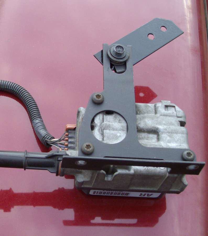
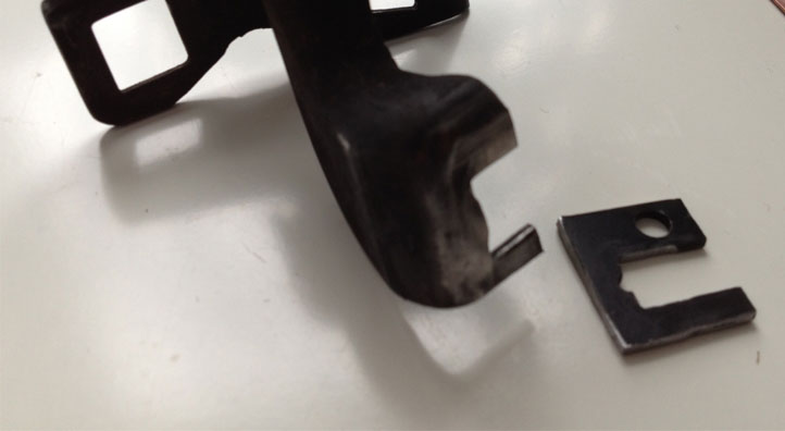
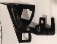
I recommend doing the mechanical installation of the module first - it makes it easier to get the wiring lengths correctly. Basically you'll take the old bracket off, transfer the two top mounting holes to the new bracket, and drill the new holes into the new bracket. Tip: take off the Torx bracket to module bolts on the junkyard, I've had bolts that were corroded to the cruise module so badly that they snapped. Since heating the module is out of the question, that module will be junk. So - be wise and make sure the bolts come loose before taking the module home.
Once the bracket is off, cut off of the new bracket what you don't need (see image to the left), and you're ready to install the bracket and module into the Fiero. I made a small adapter from a piece of sheet metal to make use of the third mounting point, using a short bolt (watch out for interference with the brake lines!). The original Fiero screw goes into the hole at the far end of the sheet metal extension, attaching it to the stock Fiero mounting point. The extra 7mm hole in the middle of the extender is a provision to install a wiring harness (rosebud) clip to keep the harness from wobbling around.
Hooking up the new cruise cable to the original throttle body is a bit of a challenge though. I got my cruise with the cable bracket still on the cable. Note: there are (at least) two different cruise cables used with the "AR" module, one has a small ball at the end of the cable, the other has a small cylinder (see image). I used the cylinder end cable and had an adapter made that connects to that type of cable (see image). You can get this adapter from Shapeways. It's a material they call bronze infused stainless steel. Unfortunately it's one of the pricier materials, but you need the strength. It's pretty tough for a 3D printed material, yet easy to work with in case you need to file something off. You can use some thread locker to glue the cylinder end to the adapter to make sure it doesn't come off, but basically that thing is under tension all the time, so it really can't fall off.
| 
| 
|
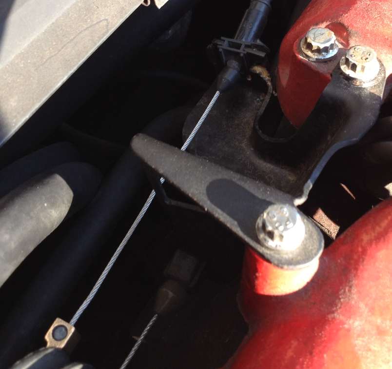
Finally, I cut a U-shaped portion of the cruise cable bracket from the donor car out that holds the cable and welded that part into the opening of the Fiero cruise cable bracket. It's important which side of the Fiero bracket you weld this part to, because it has an influence on the location of the cable sheath in relation to the throttle. You want to be able to eliminate all slack in the cable when it's mounted using the plastic adjuster that's on the cable, so weld it on the side of the bracket towards the battery. Make sure the cable clip will still fit inside the bracket before welding! If you're satisfied, weld and paint the bracket and install the cable in the Fiero.
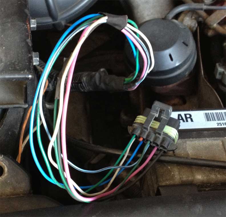
Here comes the fun part. Most signals are already on the old Fiero cruise/vacuum release connectors. I'll talk about the ones that aren't at the end. The new cruise pigtail has terminals marked "A" to "K". I'll also give the wiring colors, but these may not be correct in all years, YMMV.
We'll be cutting the wires off of the old connectors one by one and extending them as required. I crimped and soldered the extension wires, then used shrink tubing for protection. This is also a good opportunity to change to smaller diameter wires and also maybe wiring colors. I used new terminals on the end, but you may also reuse the pigtail that you have. I only reused the connector housing and TPA from the pigtail.
Begin with the ground wire at the red vacuum vent connector. The ground wire also goes to the main cruise connector from here - we won't be using that. This wire also has the perfect length to run the cruise harness above or below the cruise mounting bracket. So this length will be the reference length for all other wires. Crimp a terminal to this ground wire and put into the new connector cavity E. Crimp another terminal to the purple wire and insert it into cavity D. Get a cavity plug if you can and put it into cavity J, since we won't be using the cruise engaged lamp. Finally, splice the wire from terminal H (cruise inhibit) to the ground wire in cavity E. This is for the module coded "AR". For other modules this may or may not be required. Well, 4 out of 10 connections done, 6 more to go!
Next are the four wires from the original Fiero servo connector. Here you must extend the wiring a foot or so to reach the new connector. Lt green goes to Terminal A, dk blue to terminal B, lt blue/blk to terminal C and finally tan to terminal K. Now all that's missing are 12V power and the brake light signal. Eight down and two to go.
 So we're almost there. Only the 12V and redundant brake signal are missing.
I ran a pink wire into the trunk, behind
the trunk carpet through a 15A fuse (this is optional) to the engine blower relay, and tap into the brown/white engine
blower power supply (on an 88 you may have to find another point to tap into since there is
no trunk fan on those Fieros - but the connector may still be there). Since the engine blower relay is 20A and the cruise has a 15A
fuse on the Firebird, I put the fuse in the power line for safety's sake. But you decide
if you want to do it like that.
So we're almost there. Only the 12V and redundant brake signal are missing.
I ran a pink wire into the trunk, behind
the trunk carpet through a 15A fuse (this is optional) to the engine blower relay, and tap into the brown/white engine
blower power supply (on an 88 you may have to find another point to tap into since there is
no trunk fan on those Fieros - but the connector may still be there). Since the engine blower relay is 20A and the cruise has a 15A
fuse on the Firebird, I put the fuse in the power line for safety's sake. But you decide
if you want to do it like that.
The last wire is the infamous redundant cruise inhibit signal: "Stop lamp switch". In addition to the benefit of redundancy, wiring a relay to simulate this signal is a hassle, IMO. Instead I extended the white wire from the cruise and ran it through the trunk alongside the pink wire to the trunk fan, and from there to the right brake light. This is the way the digital cruise input was designed to be connected.
Finally put some hi-temp conduit (this is the one with a stripe on it) around the new extension harness to make things look neat, and wrap the ends with some isolating tape for reinforcement. This way the wiring will look absolutely stock, and all modifications are hidden from view and things look clean.
To summarize:
| Digital Cruise connector | Fiero wiring |
|---|---|
| A Cruise On (grey) | Fiero Servo Terminal "E" (lt green) |
| B Cruise Set (dk blue) | Fiero Servo Terminal "A" (dk blue) |
| C Resume/Acc (grey/blk) | Fiero Servo Terminal "D" (lt blue/blk) |
| D Cruise Release (brn) | Fiero Vacuum Solenoid "A" (purple) |
| E Ground (blk) | Fiero Vacuum Solenoid "B" (black - cut and discard the black wire going to the Vacuum Servo Terminal "C") |
| F Ignition Voltage Hot in Run via 15A fuse (pink) | to trunk, see above |
| G Stop lamp switch signal (white) | to trunk, see above |
| H Cruise inhibit signal (dk green) | This signal must be connected to ground when using the "AR" module. |
| J Cruise enganged lamp (white) | leave this one open and seal the cavity |
| K VSS 4000 ppm (dk green) | Fiero Servo Terminal "B" (tan) |
One big advantage of the digital cruise is the ability to troubleshoot the system using just a voltmeter at the cruise module connector. Everything from stalk signals, to clutch, brake and power signals are right there at the connector. Make sure you double check all signals work as expected after you reconnect the battery, but before you connect the cruise connector to the digital cruise module.
Since I will probably be doing this conversion on at least 5 Fieros, I built a Digital cruise tester to make the job easier. Check out if you like it!