When I had a brand new Chevy Cobalt as a rental car this year (2010), I got the urge again to add remote power locking to my Fiero. Unfortunately GM's original upgrade systems, like e.g. VSS-201, have long been discontinued, leaving only aftermarket upgrades as viable alternatives. However, I did not like the look of the fobs, they didn't look "stock".
Another thing I really enjoyed was RAP. No, not the music (I really don't understand why anyone would like that but that's a whole different story), I'm talking about "Retained Accessory Power". Basically, as most of you know, it lets you keep your radio and power windows powered even after you've removed the ignition key, until you open the driver's door. I thought it was a stupid concept, until I had it in my rental.
Both of these functions, remote power door locks and RAP, are controlled by the so-called Body Control Module or short BCM in modern cars.
In a way it's the successor of the blue chime module the Fiero has, because - you guessed it - the chime is also controlled by the BCM. Most modern cars have a BCM these days, but they often incorporate things the Fiero doesn't have or need: daytime running lights
sensor, inside temperature sensor, four doors and usually also the requirement to have a CAN or Class2 bus,
or else the module will set a gazillion error codes and not work properly. So I needed a vehicle
which does not yet have the BCM on the Class2 bus, and is as close to the Fiero as possible.
Which got me thinking: what's the Fiero's closest GM relative with remote power door locks? Right: The Firebird! Installing a Firebird BCM
in my Fiero would add all of these things and more in a single module...
So, since they're essentially the same car, I looked at the Firebirds and Camaros as possible donors. And while researching the BCM, I found the many additional benefits that come with the installation of a BCM compared the 1980's Fiero system. On the Fiero, all circuits are simple: switches controlling lamps and relays. If things get sophisticated, you get a diode to have some "advanced logic". Not so with a BCM. The BCM is a computer controlling the interior lights, parking lights, horn, door locks and supplying power to the RAP circuits (until 1995 or so there was a separate RAP module on the F-body, which was later integrated into the BCM), it also includes the Passkey II system modern ECMs require, and includes a car alarm (which you can optionally disable). And of course a remote key fob receiver, if you get a BCM with the right part number. But the nicest part is: the BCM is intelligent. Have you ever accidentally left the interior lights on overnight and drained your battery? I know I have. The BCM is smart enough to shut off your interior lights after a while to conserve battery power. Talk about redundancy: the Fiero has three separate driver door contacts: interior lights, key in ignition and door ajar. The BCM only needs one. You can customize a lot of functions the Fiero never
had to begin with:
Remote individual door unlocking
Last Door Locking
Lockout Prevention
Panic alarm
Exit Lighting
Delayed Illumination
The list goes on and on.
If you want to get an idea of the features, download the
2002 Firebird owner's manual. If you want to get an in-depth description, look at the Firebird factory service manual.
In any case, at that point I was sold: I wanted a BCM in my Fiero. But which models are suitable donors?
Picking up the parts
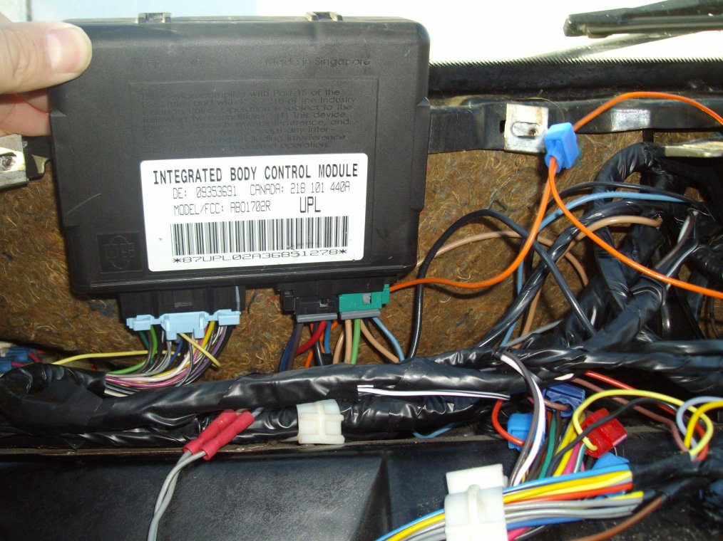
I don't know about the years in between 1995 and 1998, GM seemed to update the F-bodies (Firebirds and Camaros) quite a bit in those years with the advent of Class2 busses, etc. I wanted the latest model BCM, from a 1998-2002 (4th gen) F-body, the part number is 9353691 Code UPL. The 96-97 BCM might be compatible also, I'm not sure. But if that part
number is on it, it will work. Other (unverified!) part numbers that should work are 16239981 Code KUB and 16255931 Code DWM. Initially there were several versions (with and without remote receiver AU0), but apparently GM only sells the fully equipped version anymore, so if it has ever been replaced on an F-body in the yard, chances are it has the remote receiver even if it was not equipped with it from the factory. And being a plug-and-play upgrade for F-body owners, many have upgraded their cars with remote by plugging in this part number.
Part numbers that should work, but come without remote control receiver are 9353681 Code BAS and 16239971 Code NUR.
The BCM is easily accessible behind the glove box of a Firebird (I'm sure it's equally simple on the Camaro). It's tugged up in a plastic bracket, pull it down and be sure to also get the three connectors (and as much wiring as you can): a blue wide Micropack-100 connector with 32 pins, and two square Metripack-280 connectors with relatively large contacts (the black one is for power and the green one for power door locks).
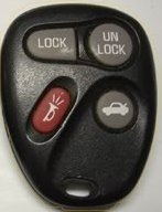
If you catch your junkyard wardens on a good day, you may end up paying $50 or even less for everything. The remote fobs are usually gone or unsightly, so do yourself a favor and get one or two new ones. GM has them, Pep boys has them, and you can get them on eBay. Take a look at them first though, the pictograms changed over the years, some have a horn button, others don't, some show a trunk lid, others say "rear", etc. If you want to be sure, get the ones for the car and year you pulled the BCM from, the picture shows the key fob for a 2002 Firebird.
The Camaro fobs come with "rear 2x" and all text, Firebird fobs sometimes come with pictograms only. I bought my fobs on eBay from Midwest Keyless for some $35.
Another choice you have is reusing the old connector terminals by splicing the Fiero wiring into the pigtails, or alternatively removing the terminals and crimping new terminals on the Fiero wiring. It's a matter of taste, really. I used new terminals where possible, and reused the old terminals where convenient. If you want to remove the old terminals from the connector housings, get the proper terminals pick(s), they make removal of the terminals really easy, unless someone has yanked on the wires and bent the tabs on the terminals. I hope you didn't do that on the yard. You can usually get the picks where the new terminals are sold.
But if you prefer a clean install over splicing and prefer new connectors, you're in for a surprise: They connectors and terminals really hard to get. I bought the blue connector from
Performance Connection Systems, the part number is 12110207 with the top secondary lock being 12045889.
The bottom secondary lock (12045890) is unavailable though PCS and I had to recyle it.
PCS also carries the female Micropack-100 terminal pins in several wire gauge sizes (12146447 and 12146448). But the two square Metripack 280 connectors (black: 12064752, green: 12089527) were impossible to get, I had to
recycle the old ones on my first installation. But again the terminals (female Metripack 280) are available at PCS (12015858, 12066214). The terminals are only a quarter or so
a piece, so do yourself a favor and buy a few extra ones, in case you ruin one during crimping (I bought 20 each). Again, you can use the junkyard pigtails if you don't mind splicing.
Funny enough, I found a supplier in Germany that carried not only the blue Micropack connector, but also the green and black Metripack 280 connectors!
Their name is DeyTrade, and they carry a wide variety of Delphi connector components
at great prices, and they also sell single quantities!
One word of caution regarding Metripack terminals: These are available as "tangless" unsealed terminals and regular unsealed terminals (with a tang). You want the terminals with a tang, the tangless terminals are intended for
tangless connectors and sit too deep in the regular unsealed connectors like the ones for the BCM!
And in case you're wondering where to get all the colorful wires I mention, it helps to have the wiring harness from almost any GM car to part out - the
colors are the same across most GM cars, and troubleshooting is a lot more difficult if all wires have the same color!
Also, don't forget to go ahead and get at least one relay. This one will work.
Checklist of items before moving on:
The BCM with connectors
Accompanied by either the cut pigtails or the Metripack terminals to make your own
A large variety of wires and your favorite product for splicing wire, for more specifics read ahead
A variety of crimp ring terminals for making ground connections
LEDs, again read ahead for more specifics
The remote. You can find new ones online for $35
At least one relay, possibly more depending on your prefrences
A set of Passkey resistors, or at least two variable resistors covering the required range
The tools
Usual Fiero interrior work, TX15, 7mm ,10mm and screwdrivers
A good crimper
Wire stripper
High quality electrical tape (which is still cheap, your Fiero is worth it)
A knife
A terminal pick or a tiny screwdriver that will work
The job looks overwhelming at first, but it's not as bad as it looks. With the dash out, you can easily get to most signals,
and the time required mostly depends on how clean you want the result to look, i.e.
if you are going for the factory look of the new wiring or if you just want things
to work.
Installing the BCM in the Fiero
Now, that part was easy, but next is the actual wiring. Do yourself a favor, and get the Fiero Factory Service Manual (FSM) at this point (not the Haynes or Chilton!), it is essential for troubleshooting. Also, get the Firebird FSM ('98-'02), you can pick them up on eBay for little money. Before you start the wiring, you need to find a good location first. The Firebird location under the passenger side dash is also a great location in the Fiero: You need access to the power door lock wiring as well as horn, seatbelt, seatbelt light, etc. All of these are right there on the so-called "convenience center". Best of all, you can get rid of the blue chime box and the power door lock relay, the BCM replaces them both. Unfortunately if you have the factory subwoofer like me, there is simply not enough space for
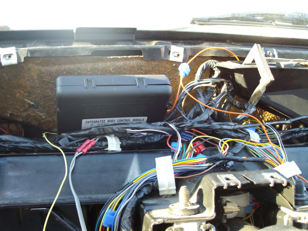
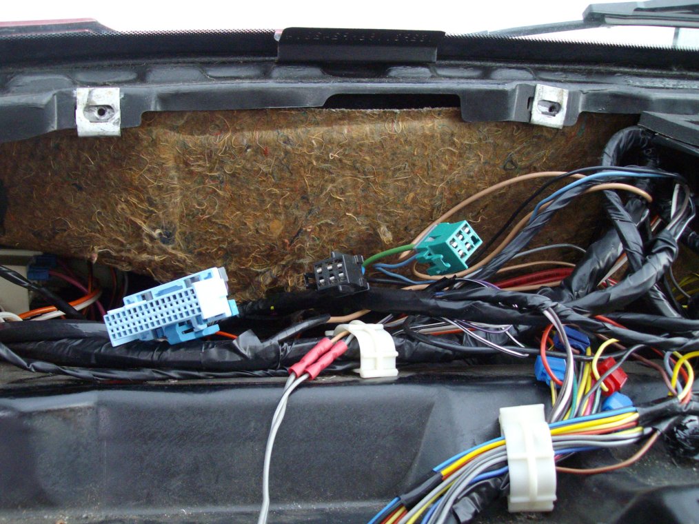
the relatively large BCM there. The alternative (which was the only option for me) is on the driver's side, on top of the steering column (see picture).
Wherever you mount it, you need to remove the dash and steering wheel. I'm not kidding. You'll be tapping in a dozen or so circuits, measuring and tracing wires and installing new ones. Taking out the dash isn't so bad, and the installation of the BCM is impossible with the dash in place. Take out the steering wheel first, it makes getting the dash out of and into
the car much easier. And one last piece of advice: disconnect the battery! You will be messing with the fuse box, and you don't want to set your Fiero on fire after all these years, do you? Be extra careful around the fuse box, it's dangerous if you screw up there.
The following description is how I wired the BCM into my 1987 GT, "your mileage may vary", follow these instructions (more of a report, really) at your own risk! The Firebird and the Fiero are closely related, wiring colors are GM standard in many cases, and I used the F-body manual as a reference as to how the wiring on the Fiero should look. Also, I wired most, but not all of the options the BCM offers. I'll discuss my choices where appropriate, again it's up to you to
do as I did or do things differently. I have also discovered the "lost schematics" - apparently GM had this planned for the Fiero a long time ago ;-). Anyway, I hope you can use them.
Before you start, I recommend removing the isolating tape on the harness running across the steering column
from the very left where it comes up from under the dash to where it disappears in the black plastic center conduit. You'll need to cut/splice/tap into most of the wires in this harness
and it makes the job a whole lot easier.
Now, we'll start with the hardest part.
Power
Well, no matter if you want to wire up all or just some of the circuits the BCM offers, it does need power. From several locations, and you need to modify the fuse box wiring. C2, the black BCM power connector handles the power and ground for the BCM (hence the large contacts), you should wire this one first.
The BCM controls power to the courtesy lights to be able to shut them down after you have left
the car. So you need to cut the courtesy lamp supply in two places: the orange wire for the
courtesy lights near S210,
(trace the driver side courtesy light back to a connector to be sure you have the right orange wire),
and the orange wire coming from the dome/reading lights going into C200 (visible near the driver side A-pillar).
Splice the end going to the dome lights together with the orange wire going to the courtesy lights, and splice a dark blue/white wire (0.8mm)
together. This dark blue/white wire goes to Terminal E of the power connector.
Extend the orange wire coming from C200 and the orange wire that was feeding power to the courtesy lights into terminal B of the power connector. The BCM connects terminals B and E to power the lamps with a relay if it allows
to power the courtesy lights.
Next we need to modify the fuse box. First we'll separate the power window feed from its neighbors. Look into the rear of the fuse box
and find the bus bar connecting the Heater/AC-Fuse, Fan-E-Fuse and Window circuit breaker.
Remove the fuses and use the blue terminal tool (or a small screwdriver) to bend the tabs on both sides of each terminal to release the bus bar.
Remove the bus bar from the fuse box. Cut a piece (1-2 mm) from the bus bar to separate and isolate (!) window circuit breaker from the other two. Bend out
the locking tabs and reinstall the Fan-E/HTR-AC bus bar. The existing orange feed wire now feeds only the FAN-E and HTR-AC fuses.
Now crimp and solder a new 3mm� dk blue feed wire into the remaining piece of the bus bar to feed the window circuit breaker. Reinstall the Window circuit breaker
bus bar. Next find the bus bar connecting Radio and Wiper fuses. Again bend locking tabs and remove bar and again separate and isolate the two. Reinstall the wiper bus bar and the existing brown feed wire.
Crimp and solder a new 3mm� dk blue feed wire into the remaining part of the bus bar to feed the radio fuse. Splice this new wire into the new wire we just installed to feed the window circuit breaker, and run it to the BCM power connector terminal C. This is the RAP output that supplies radio and windows when the ignition is off.
To feed the BCM when RAP is not active, Terminal D of the BCM power connector must be connected to a circuit that is hot in accessory and run. Use a brown
3mm� wire and run and splice it into the existing brown feed wire for the wiper fuse. Isolate the splice.
Now, to feed the BCM when RAP is active, run a new red 3mm� wire from Terminal F of the BCM power connector and splice it into the existing red feed wire of the
pwr acc circuit breaker and ctsy/lid fuse. Isolate the splice. This wire is not fused and hot at all times, so be extra careful to isolate it well.
BTW: if you connect Terminals B and E with a jumper wire, and C and D with another jumper wire, your Fiero is basically the way it was before (should you ever want to go back to no BCM, or if your BCM is broken).
Finally the BCM needs a good ground wire. Use a black 3 mm� ground wire from terminal A of the power connector and screw it to G201 (behind the radio, see FSM 201-5-C).
To summarize: the courtesy/dome lights are now no longer powered directly from the fuse box, but supply current instead goes to terminal B, through the BCM and from terminal E to the courtesy/dome lights. Window circuit breaker and radio fuse are now powered through the BCM RAP output terminal C. BCM RAP is normally supplied by the wiper feed (hot in acc or run) or if RAP is active through the pwr-acc/ctsy-lid fuse feed.
Door Locks
The next group of wires is the reason I started this whole enchilada: the door lock wiring. The BCM replaces the old power door lock relay. Disconnect the connector and discard the relay. On the connector are the wires for the door lock actuators and the door lock contacts. They go to the green BCM connector (C1).
Unfortunately we need these wires on the other side of the car, but I don't recommend extending the large diameter power wires from the connector to the BCM for
a simple reason: the wire gets too long for the driver side wire: the wire would run from the door on the left across the dash to the door lock relay on the right
and then back to the left to the BCM. The long wire would lead to an unnecessary voltage drop, costing the power door lock actuators desperately needed power.
Instead, if the wires are left the way they are (with the old lock relay connector unused but intact!), both motors are wired in parallel, running from door to door, making just an interim stop at the power door lock
relay connector. If we locate power door lock wiring harness (remember, this was an option, so there is a separate harness), we can open up the harness above
the steering column and extend the wires to the green BCM connector:
Find the 2mm� grey lock wire and splice (no need to cut the wire, just remove some insultation and crimp) in a new wire and run it to terminal B of the green BCM connector. This signal is used to lock both doors.
Find the 2mm� tan unlock wire and cut it to the left of the steering column. Pull the right end of the
wire out of the harness, and crimp a new Metripack 280 connector to it. It goes to to terminal E of the green BCM connector (passenger door).
Extend the left end of this wire with another
2mm� tan wire and run it to terminal A of the green connector. This signal unlocks the driver door.
Find the light blue lock switch wire in the harness, and splice (no need to cut) a light blue wire into the circuit and run it to terminal C on the green BCM connector.
Find the black unlock switch wire in the harness and splice (no need to cut) a black wire into the circuit and run it to terminal D on the green BCM connector.
But we are not done yet. Unfortunately the door lock switches switch to power on the Fiero, but
they must switch to ground on the Firebird system. So you need to find Splice S303 in the harness (it's also above the steering column but
toward the center of the car, see 201-16-A). The orange wire going to the right obviously goes to the right door switch. The three other orange wires go
to the left. Find C307 behind the carpet on the driver side and tug on the orange wire going to S303 to see which of the wires goes to the LH door switch.
Then cut the other two wires and splice them together temporarily (I'll get back to the new splice S303 in a moment). Now the door switch supplies have been separated from the power mirror supply and
the CTSY/LID fuse. Connect the LH and RH door switch supply wires together and isolate them. Finally splice in a black wire to ground
(I used the now unused ground screw previously used for mounting the door lock relay) into the door supply circuit.
Verify terminals C and D on the green connector go to ground when the appropriate lock/unlock buttons are pressed. Now the two "big" connectors have been wired, and all that's left are the small diameter wires going to the blue Micropack connector.
You can use thin (0.5/0.8mm) wires from now on as indicated in the schematics.
Now let's get back to S303, the CTSY/LID fused supply that now only feeds the power mirrors. This splice is hot at all times. This is fortunate, since
we'll need a point to tap into "hot at all times" for a few circuits in this upgrade, e.g. diagnostic lamp, parking lamp relay feed, shock sensor, etc. So I used an isolated
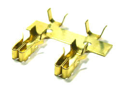
clamp until the very end of the operation before crimping these together with a splice crimp terminal part number 1839906 and isolating the new S303
well with the old isolation tape.
BTW, Terminal F of the green connector is marked unused in the F-body manual, but it really is an antenna input! I don't know why GM decided not to use it,
you can greatly extend the range of the receiver if you install an antenna here. Just get exactly 47cm (18.5") of isolated wire and
crimp a Metripack 280 connector to it, and insert it into terminal F. Route the wire across the car and if necessary isolate the end,
because it may not touch any other conductor or ground!
Chime box functions
As I mentioned before, the BCM also replaces the blue chime box (aka the "audible alarm center"). So it is only natural to get the signals from the convenience center (which is
where the chime box is usually plugged in). The chime box is behind the dash on the passenger side. If you have the factory sub equipped, it will be hidden behind the subwoofer housing. You can pick up quite a few signals at the
convenience center:
C1 - Ground. This is terminal "G" at the convenience center.
C4 - Fasten seat belt indicator. This is the yellow wire terminal "F" at the convenience center.
C13 - Seat belt switch. This signal is the black wire terminal "H" at the convenience center.
C14 - Key in ignition signal. This signal is the light green wire terminal "C" at the convenience center.
D5 - Ignition from Gauges fuse (hot in run, bulb test or start). This signal is the pink/black
wire at terminal "E" of the convenience center.
D15 - Park lamps feed: connect this wire to any brown "park lamps" wire on the cross car wiring harness, e.g. at the light switch.
Cut these wires between the convenience center and the center of the car (right before they disappear in the center plastic conduit is
a great place to cut), and pull them back through the harness and connect them to C1, C4, C13, C14 and D5 of the BCM connector. They're long enough to crimp a new terminal to each of them and insert into
the connector directly, so no splicing or extending for a change.
The parking lamp input on the Fiero is wired with the IP illumination (terminal A/grey wire on the convenience center), which would probably work as well, then you can turn off the parking lamp warning by dimming the
IP lights. On the Firebird D15 is connected to the "park lamps" circuit (brown wire) and not the IP illumination circuit. I tapped into the park lamps circuit at the light switch.
Since the horn relay is in the same harness going to the convenience center, find the (right) black wire in that harness and splice a wire and route it to C9.
Unless you don't want to control your horn remotely, in which case you can skip this step.
Trunk release
Okay, the trunk release circuit is a little different than the Fiero's but not completely different. You do need to wire in a new
(standard) relay though. I used the trunk relay from a '95 Firebird, including the proper relay socket.
First you need to cut the orange/dk blu wire and the grey/black wire at the trunk release switch, and
connect them thus bypassing the trunk release switch. Connect the grey/black wire of the switch to the black ground wire at the switch.
Finally splice a new wire into the orange/dark blue wire and run it to terminal D3 on the BCM connector. Now the BCM sees the trunk signal from the release switch.
Next we work on the new relay. Find and remove the old relay. Cut the wires at the trunk relay connector
and be sure to leave enough wire on the connector to reuse it later on. Then crimp new Metripack 280 terminals to the wires. Insert the
wires in the new relay socket like this: One working contact to the grey/black wire (power), the other working contact to
the black/white wire (output to trunk solenoid). Then insert the tan/white (manual) or yellow (automatic) wire to one end of the coil,
and splice a new wire into the remaining wire (you can keep the one already in the socket if you have a used one with a pigtail)
and connect it to terminal D4 on the BCM.
If you use the Hella relay mentioned earlier grey/black goes to "87", black/white goes to "30", tan/white or yellow to "85" and the wire from D4 to "86".
Diagnostics
As I mentioned the BCM is smart and contains diagnostics, just like you can jumper A&B on the ALDL connector and the ECM flashes the service engine soon lamp. The BCM has a very similar feature, and I highly recommend wiring it.
One part is the diagnostic input. Believe it or not, diagnostics is initiated by pulling the RADIO fuse! Wire a yellow wire from D6 on the blue connector to the radio fuse circuit (fused side), e.g. at the Radio (duh!) or the
fuse box. Now you can initiate diagnostics, but you can't see the result yet. Well, the lamp the BCM flashes is the security indicator lamp (C12), which you can add to an unused idiot light
in your dash (e.g. shift up light on automatic Fieros, or the battery light on rally gauge equipped Fieros). The other end of the light must be connected to battery power "hot at all times" (remember our new splice S303?)! This is important, because the BCM wants to turn on the security light even with
the ignition off or in ACC for diagnostics. If you don't care about another idiot light in the dash,
you can mount the lamp anywhere, even behind the dash, as long as you can see it
if you want to run diagnostics.
If you don't want to mess with the instrument cluster, you can also install a lamp (or a small LED with the proper series resistor) some place else.
Interior/exterior lights control
We have already wired the interior lamps feed with BCM power connector C2, now we need to wire the interior lights return.
First of all, find S304 (it's the one with four white wires), one going to the right and three going to the left.
Cut the single wire going to the right about 1" from the splice. Splice a new white wire into the wire coming from the right - this is the passenger
door jamb switch. Extend the switch end of the wire to the D12 terminal (passenger side input) of the BCM connector.
Next is the LH door jamb switch. This is one of the remaining three wires going into splice S304. I removed the switch from the door and tugged
on the wire to "feel" it. Anyway, cut the wire as close to the S304 as possible and isolate the S304 side you just cut.
Now splice a new wire to the switch end of the wire and connect the new wire to the D11 terminal (driver side) of the BCM connector. This is
so the BCM can sense if either door is open, and which.
Also find the tan wire at the driver door jamb switch and connect it directly to ground.
Next find C209. One half goes to the courtesy lamps, the other end goes to the harness. It has two identical wires.
Now you'll need to take a 50/50 chance.
If you don't want to cut and then use an ohms meter to see if you got it right, you can trace the two wires back to the larger bundle of wires,
one goes towards the driver side and the other towards the passenger, cut the one going towards the passenger side.
One of the two white wires goes to the IP dimmer switch. Cut one of the white wires 1" away from the connector and check which one goes to the IP
dimmer switch. If you got the wrong one, cut the other one and reconnect the one you cut first. Extend the end that is connected to the dimmer switch
to C7 on the BCM connector. This lets the ip dimmer switch command the BCM to turn on the interior lights, and lets the BCM turn them
off if you run down the battery.
Finally, there is still 1" of white wire coming out of S304 that you cut three paragraphs ago. This is the courtesy lamp return. Extend it with a
white wire and connect the other end of the wire to D1 on the BCM connector.
Now the BCM can turn on and dim the courtesy lamps.
One word regarding D13: this is the rear compartment ajar input. It is used to turn on the courtesy lights on the Firebird if the rear deck is ajar. While this may make sense
on the Firebird, it doesn't make sense on the Fiero, so leave this input open! On the Fiero the trunk is obviously separate from the interior, so the
lamp and switch are on a separate circuit from the interior lights on the Fiero. This also means the trunk lights are not controlled by the BCM and you
can still drain your battery if you leave your trunk ajar! If you want to wire your trunk light into the BCM controlled interior lights, separate the
trunk ajar switch from the splice of the door and hood ajar switches and wire it to D13 instead. You will lose the trunk ajar idiot light this way, but
the trunk ajar will also light your interior lights now. In order for the BCM to turn power off to the interior and trunk lights if left on unintenionally,
you need to separate the orange/dark blue trunk light feed wire from Splice S125 and splice it into the dome light power feed instead.
The BCM also controls the exterior lights: it can flash your parking lights when you lock or unlock your vehicle.
You need another external relay for this, blue connector terminal C8 goes to one side of the relay, the other side goes to the PWR ACC fuse.
The same fuse also feeds the relay, the output goes to the parking lights. But you can also use our new S303 for feeding the relay.
If you saved the trunk relay from earlier you can use that one. The hot wire from S303 (or elsewhere if you desire, just needs to be hot
at all times) goes to the grey/black wire, any of the brown parking light wires goes to the black/white wire and C8 goes to the tan/white or
yellow wire, depending on manual or automatic.
If you want the turn signals for signalling instead, use a relay with dual separate outputs,
and wire them to the LH and RH turn signal circuits. With a fastback you can connect front and rear turn signal circuits at the turn signal switch,
on the notchback you'd have to use two relays or a relay with four outputs.
Vehicle theft deterrent (VTD)
The remaining features of the BCM are more or less optional. If you want the security indicator/diagnostic lamp to be off (and most people will), you need to determine the correct Passkey II resistor to connect across D7/C2 of the blue connector. Of course you can also install a new lock cylinder, but this is
beyond the scope of this article.
For now, just install two wires, run them to the steering column where you can access them later. You can also install a hidden connector and plug a resistor in there, your imagination is the limit. Just as long as the BCM sees the proper Passkey resistor. Try out all possible values (see Passkey table) until the lamp goes out. Attention: after reading a wrong resistor value, you need to wait 4 minutes before you can try the next value! If you install a functional Passkey system, you need to wire in a theft deterrent relay of proper rating to
interrupt the starter control line in series with the clutch or park/neutral switch. The relay coil ground
comes from the BCM pin C11, the coil power comes from the ignition switch starter terminal.
Finally D8 is a fuel enable output signal most newer ECMs require. The BCM generates a sqaure wave here if the correct Passkey resistor was read. Connect it to your ECM's fuel enable input, if you have swapped in a
suitable ECM, but normally you can leave it open.
Content theft deterrent (CTD)
Maybe more interesting than the Passkey system is the optional alarm system the BCM offers. How does the
BCM know if the vehicle is equipped with an alarm system? Simple: the BCM checks if a security LED is connected
to it. If this is the case, it logs a diagnostic code 25/35, and enables the alarm features. Even if the LED
is no longer connected, the history code 35 will still be there and you will keep your alarm system, at
least until you clear diagnostic codes! If you happen to do that, the code 35 will be gone, and your BCM
thinks you're no longer equipped with an alarm system. Funny, huh?
Anyway, at the cost of a LED it's simple to add a red LED, connect C16 to the anode of the LED
and the cathode to ground. No series resistor, this is already contained in the BCM!
One nice place to mount the LED is in the defroster grille, using a 5mm LED and plastic clip (thanks to Keelan Carpenter for this tip!)
The LED will flash if the alarm is armed to deter thieves, and if the system is armed and a door is opened, the alarm will sound.
If you end up not liking the alarm system, you can disable CTD through vehicle personalisation. But at the cost
of a LED, I'd suggest wiring it.
Shock sensor
Terminals D2/D14 allow you to hook up an optional shock sensor to be used with the CTD, and these terminals are for shock sensor and tamper switch signals.
Maybe you like the idea of your alarm going off if it's windy - maybe you don't. In the latter case, just leave the inputs open.
You can also use these BCM inputs to wire aftermarket equipment, like an interior radar sensor if you like to park with the
windows open. The tamper input makes the BCM "chirp" the horn if it goes to ground, the shock input triggers
a full alarm if it is grounded.
If you do decide you want the F-body shock sensor, make sure you get the right part number: 10440241 is the third generation shock sensor,
10444928 will work too. Do NOT use P/N 10430551
as this is the second generation sensor that can go off without any reason! Part number for the mating connector is 12064760,
you will also need two TPAs (15324070). Tip:
This particular connector was used extensively by GM for power mirrors. They're easy to find in a junkyard.
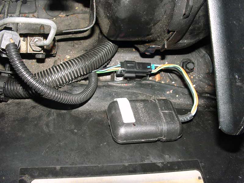
First, you need to pick a mounting location. I suggest the front compartment, e.g. above the spare tire or on the wheel well (see image).
On the Firebird it was stuck on the wheel well with double sided tape (no kidding!). But how do you get the wires to the front compartment?
Well, if you carefully look at firewall connector C100, you'll see that some positions are not used.
You can insert the proper connectors into these two and
use them to feed wires to the front compartment in a clean way. Getting to the bulkhead connector may seem difficult at first,
but it really isn't. There's a 1/4" bolt holding the connector together (just like the one at the battery that I'm sure you've
already had apart a dozen times). Then you can separate the two connector halves, the upper one going to the A/C and blower you can
leave alone. The lower one is the one we care about. There is a secondary terminal lock that you absolutely need to remove. It's
probably covered by the black goo.
This thing is going to be messy! The dielectric grease (goo) has probably
turned to tar over the last 25 years, but brake cleaner can do wonders. Clean the outside of the connector until you see a white
"bar". You need to extract this bar from the connector with a small screwdriver. The goo will make it difficult to get it out,
but once it's moving, you should have it out quickly. Then clean the three connector cavities you're going to use
with a thin screwdriver or terminal pick. Use Metripack terminals (280, 450 and 630) for the three wires of the proper colors.
I Wired BCM terminal D14 to Fiero's C100/H7 (green wire).
Since C100/F7 is only used on the L4 with two speed fan, it can be used to connect to BCM Terminal D2 (lt blue wire).
Finally you need to find a ground and "hot at all times" power for the sensor. Ground is simple: use G101 on the LH fender.
Power is not so simple. G6 and G8 are hot at all times, but not fused (fusible link only). F8 is powered and fused, but
only hot in run. Fortunately G7 is unused unless you have an 88 with electro-hydraulic power steering. If you do, you are
lucky but a minority. The rest of us can use an orange wire
to C100/G7, and patch it into a circuit that is hot at all times - remember our new splice S303? Anyway, now you
can already reinsert the secondary lock. Crimp female unsealed Metripack 150 terminals to the four wires, and insert them into the proper connector housing. That's all in the front compartment, now you need to work behind the brake pedal.
You'll see the other side of the bulkhead connector when you look behind the brake pedal with a flashlight. There are two 7mm bolts
holding it to the firewall. Those bolts are looooong. Once they're out, you can pull the connector out and lay it on the floor to
work on quite comfortably. Again you'll need to remove the secondary lock, but this time there is no or very little goo.
Insert the three wires with male metripack blades and reinsert the secondary lock. Reinstall the connector in the bulkhead and
reconnect the mating connector in the front compartment. Check the wires for continuity and make sure you got the colors right!
Lamps or LEDs?
The BCM controls the Security light and the seatbelt light but on the 98-02 Firebird
cluster these lights are actually LEDs, where on the Fiero they are standard lightbulbs. The difference? Well, the lightbulbs produce several watts, and thus
draw much more current than the LEDs. Frankly, I'm not sure if the BCM can handle
the current for a lightbulb without taking damage. It's difficult for me to get a
new BCM if my old one is shot, so I didn't take a chance and installed LEDs in
place of lightbulbs for these two idiot lights. I did find the schematics of this
BCM in connection with the 96 Firebird cluster, and in that year the cluster apparently still contained bulbs, but I'll leave that experiment for someone else
to try. Please let me know if it works though, and you'll get an honorable mention.
Testing
Before hooking up the BCM, I ran a couple of tests which I list here in case you too want to test your
work before connecting everything. The tests don't test every single possible condition, but are a good
first test that can be done with little effort to verify your installation.
The first part of the tests should be performed with the battery disconnected.
Use an Ohmmeter to verify these terminals are grounded (a continuity tester works too) at all times, or
grounded when the given condition is true:
C1 (green) C: lock switch driver and passenger door pressed (test both sides)
C1 (green) D: unlock switch driver and passenger door pressed (test both sides)
C2 (black) A: Main ground
C3 (blue) C1: Signal ground
C3 (blue) C7: IP dimmer switch: interior lamps on
C3 (blue) C13: Seat belt unlatched
C3 (blue) C14: Driver door open AND key in ignition
C3 (blue) D3: Trunk release switch pressed
C3 (blue) D11: Driver door open
C3 (blue) D12: Passenger door open
Also verify D2, D13 and D14 are not grounded! If you have the Passkey system hooked up, verify the resistance between C2 and D7 reads correctly on the Ohmmeter.
Next hook up the battery with the BCM still unconnected. Verify there is no smoke anywhere. Use a test light or
voltmeter to verify battery voltage at these connections under the given ignition key position:
C2 (black) B: Hot at all times (except if courtesy fuse is not in)
C2 (black) D: Hot in ACC/RUN only
C2 (black) F: Hot at all times
C3 (blue) D5: Hot in RUN/Bulb Test/Start (except if gauges fuse is not in)
C3 (blue) D15: Park lamps on
The next tests involve a fused jumper (5A max). Touch the connector terminal only momentarily to avoid
possible damage and observe the unit for correct operation. First connect one end of the fused jumper to ground and test these terminals:
C3 (blue) C8: Parking lights should come on
C3 (blue) C9: Horns should sound
C3 (blue) C12: Security lamp in cluster should come on
C3 (blue) D4: Trunk unlocks (note that other conditions need to apply, i.e. parking brake set and shift lever in park!)
Finally use a fused jumper to battery for these tests:
C2 (black) C: Radio is supplied power through RADIO fuse (you may want to use a 15A fused jumper for this test depending on your stereo system!). While the jumper is in place, verify D6 shows battery power (12V)
C2 (black) E: Map lights come on if map light button is pressed
C2 (black) E: With C2/E powered, ground D1 (this is the interior lamp control): the courtesy lights should come on
C3 (blue) C4: Seatbelt lamp should come on
C3 (blue) C16: Theft deterrent LED should come on. Caution: You need to run this test with a ~500 Ohms resistor in series of you will blow the LED!.
These pins are not tested with these tests:
C1 (green): A, B and E (power door lock motors, needs two jumpers for testing, and a bit of current too)
C3 (blue): C11 is the theft deterrent relay (which doesn't make sense unless you wire the Passkey components)
C3 (blue): C15 controls the low coolant light latch (which the Fiero doesn't have)
C3 (blue): D8 carries the Passkey fuel enable signal (signal is generated by the BCM and Fiero ECM doesn't use it)
C3 (blue): C3, C5, C6, C10, D9, D10 and D16 are not used
If all these tests succeeded, you can dare to plug in the BCM. Remember, some terminals carry unfused
battery power at all times, so it's a good idea to disconnect the battery for the installation of the BCM.
First, enter diagnostic mode as described in the FSM and check for current or history codes. Remember, you
don't know if the previous owner had BCM problems before the car went to the yard! Clear codes, and check the
customizable features, you never know what the previous owner had set. If any error codes remain, diagnose
them as per the Firebird FSM. While the BCM is in diagnostic mode, it sounds a single "ding" for each
input changing state, e.g. if you open or close a door. This is very useful for diagnostics once the BCM
is hidden behind the dash.
Security indicator
The security indicator is valuable for diagnosing any problems with the BCM, but chances are you had powered
the BCM at some point with the Fiero ignition on, but no passkey resistor installed. If a correct resistor
had previously been seen by the BCM (i.e. the BCM is not brand new), and the sensing inputs are open with
the ignition in run, the BCM may enter fail mode.
Basically the BCM thinks your passkey system is defective. The BCM is in fail mode if the security
indicator is on when the ignition is in run, but goes off if you turn the ignition off. In this mode, even
if the correct resistor is connected, the light will not go off after a few seconds like it should.
To get rid of the annoying light,
insert the key into the ignition with the correct or just about any valid resistor value connected
to the BCM, and set the ignition to "run" for 3 minutes, then turn it off. This should make the BCM exit this fault mode,
and if you have the correct resistor connected, the light should go off. If the resistor is wrong,
the light will go on again, but stay on when you turn off the ignition. This is the difference
between this failure mode and the previous fail mode. So turn off the ignition with the security light on,
wait 3-4 minutes until the light goes off, connect the next resistor and THEN turn the ignition to run. Repeat this process until you have found the right resistor.
Final words
Well, that wasn't so bad, was it? I had the dash out for about a week and I only did a few wires a night because
it was raining and I had to document everything. With the information in this article you should be able
to do this upgrade in a fraction of the time.
I take no responsibility that what I wrote here works on your car too! Whatever you do, you do it at your own risk. But if you perform this major upgrade,
I'd like to hear from you, and of course please also let me know of any mistakes you find in this document.
 I don't know about the years in between 1995 and 1998, GM seemed to update the F-bodies (Firebirds and Camaros) quite a bit in those years with the advent of Class2 busses, etc. I wanted the latest model BCM, from a 1998-2002 (4th gen) F-body, the part number is 9353691 Code UPL. The 96-97 BCM might be compatible also, I'm not sure. But if that part
number is on it, it will work. Other (unverified!) part numbers that should work are 16239981 Code KUB and 16255931 Code DWM. Initially there were several versions (with and without remote receiver AU0), but apparently GM only sells the fully equipped version anymore, so if it has ever been replaced on an F-body in the yard, chances are it has the remote receiver even if it was not equipped with it from the factory. And being a plug-and-play upgrade for F-body owners, many have upgraded their cars with remote by plugging in this part number.
Part numbers that should work, but come without remote control receiver are 9353681 Code BAS and 16239971 Code NUR.
I don't know about the years in between 1995 and 1998, GM seemed to update the F-bodies (Firebirds and Camaros) quite a bit in those years with the advent of Class2 busses, etc. I wanted the latest model BCM, from a 1998-2002 (4th gen) F-body, the part number is 9353691 Code UPL. The 96-97 BCM might be compatible also, I'm not sure. But if that part
number is on it, it will work. Other (unverified!) part numbers that should work are 16239981 Code KUB and 16255931 Code DWM. Initially there were several versions (with and without remote receiver AU0), but apparently GM only sells the fully equipped version anymore, so if it has ever been replaced on an F-body in the yard, chances are it has the remote receiver even if it was not equipped with it from the factory. And being a plug-and-play upgrade for F-body owners, many have upgraded their cars with remote by plugging in this part number.
Part numbers that should work, but come without remote control receiver are 9353681 Code BAS and 16239971 Code NUR.
 Next we need to
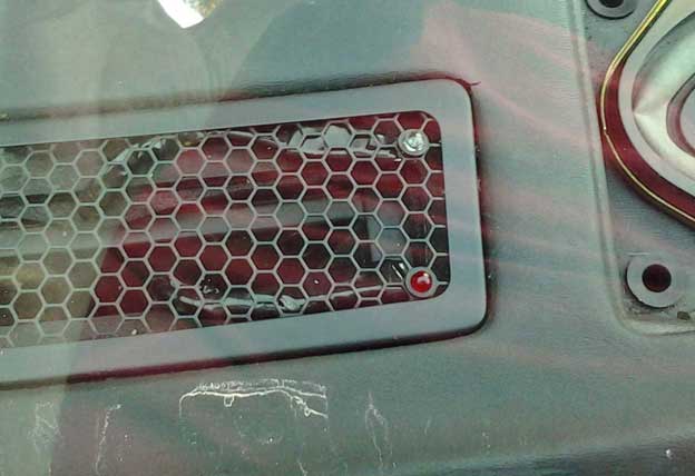