 When you work with pretty much any protocol, you need to be able to watch what's
going on on the network. So a protocol analyzer was needed. I wanted to be
able to convert the J1850 telegrams to RS232 to use on any computer, but
my COM ports are usually in use, so I decided to put an ethernet port on the
device as well. I based the design on the Motorola MC68HC912B32, which has
a BDLC (J1850 module) on chip, and together with an external transceiver chip
that's all the hardware necessary for J1850 interfacing. The ethernet interface
is handled by the CS8900 chip by crystal semiconductor. It was really difficult
to acquire that chip and the associated parts; I actually found the CS8900 on eBay!
Don't ask me how I liked soldering that bastard... soldering the 100 pin fine pitch
without a microscope, with a regular soldering iron was a challenge!
When you work with pretty much any protocol, you need to be able to watch what's
going on on the network. So a protocol analyzer was needed. I wanted to be
able to convert the J1850 telegrams to RS232 to use on any computer, but
my COM ports are usually in use, so I decided to put an ethernet port on the
device as well. I based the design on the Motorola MC68HC912B32, which has
a BDLC (J1850 module) on chip, and together with an external transceiver chip
that's all the hardware necessary for J1850 interfacing. The ethernet interface
is handled by the CS8900 chip by crystal semiconductor. It was really difficult
to acquire that chip and the associated parts; I actually found the CS8900 on eBay!
Don't ask me how I liked soldering that bastard... soldering the 100 pin fine pitch
without a microscope, with a regular soldering iron was a challenge!
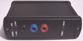
The bridge
So, my analyzer was supposed to be simple and easy to use. In the back there are the RS232 and Ethernet (10BaseT) ports, in the front there are three connectors for power, ground and the J1850 bus. Additionally there are 6 LEDs for various purposes:
- Power (blue) - Well, you need to be able to tell if there is power, especially since there is no switch
- Status (yellow) - flashes when the software is running, stops if the software hangs. This was useful during development, but still is if I make changes.
- Link (green) - on if the Ethernet is connected
- LAN (yellow) - on if there is traffic on the LAN
- RS (red) - on if there is traffic on the serial port
- J1850 (yellow) - on if there is traffic on the J1850 bus
The unit can be configured via RS232, this includes the ethernet address (sorry, no DHCP support). For now, every J1850 telegram that is received is sent to both Ethernet and RS232, and telegrams are accepted from both ports as well.
The accompanying software (initially DOS only) was written in C/C++ as a cmdline tool that can translate J1850 messages with the help of a configuration file into sensible text. It also allows me to transmit predefined messages on a keystroke.
With the progressing development of the DCM I needed a more user friendly way of diagnosing the DCM, which led to a COM-Plugin allowing me to use the J1850 bridge from Visual Basic, and then a VB application for recalling Diagnostic Trouble Codes, clearing them, reading ports and variables, etc.
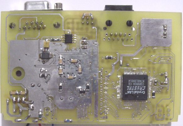
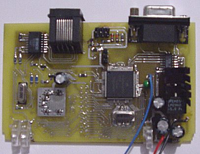
The circuit
Well, if you are interested, here's a peek at the bridge's circuit board. The main components are the CS8900 on the solder side and the Motorola MC68HC912B32 on the component side. The J1850 transceiver is the small 8-pin SMD part on the solder side. You can see the 6-pin programming/debugging connector between the two jacks if you look closely. The (now) unpopulated two rows of 10 holes each were used to connect a CS8900 subassembly board that was known to work until the software had been written.
| 
|